Today we'll discuss 32-bit microcontrollers with ARM Cortex-M cores and, in particular, STMicroelectronics (aka ST) controllers. This post will describe how to develop for these controllers, which development environments available, and how to use some popular libraries. If you are interested in Arduino development, but 8-bit AVR is no longer enough for you, and you want something more, then this post is for you.
So, imagine that you have successfully worked on an 8-bit AVR Arduino project. Maybe you even have some completed devices. You definitely noticed that the AVR8 controllers are quite simple and cheap, but they provide not as much features, and they do not run very fast. So what's the solution? That's right: look for more advanced controllers! And, fortunately, there is a bunch of them: these are controllers based on the ARM Cotrex-M architecture.
There is a whole family of ARM architecture variants, and they are all designed for different purposes. There is ARM Cortex-A for applications like full-fledged OS (yes, these are often used in smartphones), Cortex-R for real-time systems and systems where a high level of security is required, and, finally, Cortex-M - designed exclusively for microcontrollers. There are even older cores (like ARM7TDMI), but the three I mentioned are modern ones. There's a decent video which describes the characteristics, internals and differences of these cores.
We will only consider Cortex-M architecture cores, since they are used by manufacturers like ST, NXP and Microchip to build microcontrollers. However, there are many Cortex-M core variants developed by the ARM Corporation (Cortex-M0, Cortex-M0+, Cortex-M3, Cortex-M7, etc.), a full list can be found on Wikipedia. These cores differ in the supported instruction sets, pipelines, the support of features like FPU, MPU, etc. The license for the particular core is purchased by a specific manufacturer from ARM, then various peripherals are added to it (timers, DMA, all sorts of interfaces like SPI, USB and I2C, etc.), everything is placed on a silicon chip, and finally, you can purchase a microcontroller and work with it.
By chance, I had an Open103Z debug board with the STM32F103ZET6 controller.

This controller is based on the Cortex-M3 core, which is now very popular among available ARM microcontroller cores. Controllers with this core are inexpensive, the cheapest one you can buy is probably less than 1 USD, and the cheapest one made by STMicroelectronics is about 1-1.5 USD. You can purchase them even cheaper on Ebay/Aliexpress, but they are possibly not genuine. STM32F103ZET6, which is used in the Open103Z board, costs more, about 8-10 USD, since it’s an advanced one with large memory banks and many different peripherals and interfaces. However, the code written for this controller is still easy to port to other ST controllers on the same core (unless, of course, you use some unique peripherals that aren't supported by a cheaper version).
There is even Arduino Due with the ARM Cortex-M3 controller on board. The controller is AT91SAM3X8E, made by Atmel (which is now Microchip), but the core is still the same Cortex-M3.
But back to my debug board. Since I had it, I decided to dive into this topic and write some code for the controller. Previously, I didn't have an opportunity to work with ARM microcontrollers at all, so I started by reading a large number of articles and datasheets. It turned out that the ARM development topic is extremely popular. A lot of people build their own projects, write posts and make videos and discuss various issues on forums. I've read a lot, understood something, but still was a little confused. There is a pile of development environments and compilers, some mysterious acronyms like CMSIS, SPL, HAL, LL, linker scripts, libraries, etc. This wasn't improving my understanding at all! So I had to dig even deeper, and now I'm ready to share this knowledge in a more or less clear and, most importantly, structured form.
Question 1. Which controller should I buy?
Purchase any with the Cortex-M3 core from STMicroelectronics. They are cheap, popular, rich with peripherals. Cortex-M4 and Cortex-M7 cores are faster, more advanced, complex and expensive, you probably don't need them yet. Cortex-M0 or Cortex-M0+ cores are older and slower than Cortex-M3, while typically cost the same. Look at peripherals (DMA, timers, PWM, etc.) and interfaces (SPI, USB, I2C, UART), in case you need something specific. Check the maximum operating frequency (most of ST controllers operate at 72 MHz, which is several times faster than AVR8 controllers can handle). STM32F103C8T6 or STM32F103RBT6 are great options for the money, 64/128 KB of program memory, 20 KB of RAM, a bunch of useful peripherals (DMA, timers, watchdog, USB, I2C, SPI, UART, CAN, ADC, CRC, etc.), 72 MHz is the maximum core frequency. There's a disadvantage though: it's difficult to solder such controllers manually, because they are not available in DIP packages, but are available only in LQFP, which is difficult to handle even when using dry film photoresists.
Fortunately, there are a lot of debug boards with different ARM controllers, in case you do not want to solder anything yourself yet. Specifically, there are many of them with ST controllers. For example, here are affordable debug boards with ARM Cortex-M3 controllers on Mouser. I'm sure it's easy to buy such boards from your local supplier. They are also available from Ebay or Aliexpress. Type the "stm32 arm cortex m3 development board" query on Ebay, and you'll find many cheap options with the above mentioned STM32F103C8T6 and STM32F103RBT6 controllers.
Question 2. I bought a controller or a board, what do I do next?
You may also need a programmer to program and debug your chip. If you decided to go with a standalone controller chip and solder it yourself, then you'll definitely need one. Otherwise, this depends on debug board type you purchased. Arduino Due, for example, does not require it, everything is already built into the board. ST Discovery boards usually have a built-in programmer, as well. My board doesn't have any, so I got an STLink/V2 programmer (remember, I'm mostly writing about ST controllers, because I worked with them), which supports any STMicroelectronics controllers (STM32 we're interested in, and STM8 as well, which I don't cover in this post). A genuine programmer can cost around 30 USD, although you can buy a Chinese clone for only 2.5 USD on Ebay. ST controllers usually support debugging and programming via JTAG and SWD interfaces (Serial Wire Debug). STLink/V2 can work with both of them.
Next, you need to choose the development environment. There are a lot of them: Arduino IDE, Eclipse (or even its modification from ST), Keil MDK ARM (paid, only small programs can be compiled for free), Visual Studio + VisualGDB (paid, but definitely worth the money), IAR embedded workbench (EWARM) (paid, only small programs can be compiled for free), Mbed studio (free, made specifically for Mbed development, which I'll discuss later), and others. You can even code in notepad and compile the code using Makefiles, invoking the gcc toolchain directly. You can download the toolchain used by Eclipse from GitHub - this repository is now archived, use this one (xpack-dev-tools). Many environments often provide some of their built-in libraries for implementing popular features (all kinds of USB devices, for example). However, this is not so important, as STMicroelectronics also provides the same free libraries for its controllers. You'll be able to use these libraries in any environment. Let's talk about this in detail later.
I can't really say anything about Eclipse and IAR, because I haven't used them. Keil MDK allows to quickly compile code for the desired controller, immediately flash and debug your chip. Arduino IDE is pretty much the same, but only works with Arduino Due. You can install Arduino Core STM32, then it'll be possible to write code in Arduino environment for a bunch of other debug boards with ST controllers. I personally don't like Arduino environment, as it doesn't allow to easily change compiler and linker options. Visual Studio + VisualGDB is a very convenient option, because it allows you to write, compile, flash and debug the code entirely in Visual Studio. There's also syntax highlighting and custom IntelliSense. VisualGDB costs only 100 USD for embedded development (compared to more than 1500 USD for Keil MDK). I think, in general, all options are more or less the same, and your choice should be based on your personal preferences. I settled with VisualGDB with xpack toolchain, as well as a bare Makefile option.
Now let's discuss development for STMicroelectronics controllers. There are several free utilities for these controllers that will help. The first is STM32CubeProg. This is a programmer software that supports all STM32 microcontrollers. It allows you to write and read controller memory, edit it, change controller configuration bits, and flash the controller memory. The utility is useful if you want to compile the code using a Makefile and regular gcc, without any sophisticated development environments.

The second useful utility is STM32CubeMX. It has a convenient graphical interface and allows you to generate basic initialization code for any of the ST controllers. This code will configure the clock frequencies of your controller, the I/O ports, the required peripherals, and also create project files for the selected programming environment. It will also prepare a linker script for your controller, which we'll talk about later. Keil MDK-ARM, IAR EWARM, as well as Makefile projects are supported, along with several less popular environments. The generated code will utilize HAL - a modern ST-owned software library. We will talk about useful libraries later. Basically, you create a project via STM32CubeMX, generate initialization code for the required development environment, and then open the generated project in this environment and add the code that you need. There are some disadvantages: when you regenerate the code (for example, if you need to change the peripheral or other controller settings), the existing files (which you may have changed already) may be overwritten. You'll have to merge the changes manually if you have already changed something in the autogenerated files. In addition, you will be forced to use the HAL library, since all the code generated in STM32CubeMX uses it already.
STM32F103C8T6 controller peripherals configuration:

STM32F103C8T6 controller clock setup:

Both utilities, STM32CubeProg and STM32CubeMX, are absolutely free.
Question 3. What libraries do I use to code faster and easier?
So, you've installed a development environment and probably STM32CubeMX. The next question that you'll have in mind is: "What libraries should I use to quickly get something working?" So, what do the open-source community and ST offer to the developer?
- CMSIS. This is the fundamental library for ARM microcontrollers. It is being developed directly by ARM. It generally supports any controllers with any ARM core, and includes various universal definitions for these cores. For example, there are interrupt management routines, features common to many ARM controllers, such as SysTick configuration, memory pages protection management (if it's supported by the controller), optimized math functions, etc. This library supports every compiler and works in every development environment. Often, when creating a project for an ARM controller, the development environment will automatically add the necessary CMSIS header files, and you won’t have to download and include them manually (unless you want to use the latest version that you have to download from GitHub). CMSIS also offers controller manufacturers some templates that they can use to include their own code in CMSIS and implement peripheral support in a unified manner. Basically, CMSIS is a standard interface, which can be implemented by a microcontroller manufacturer. STMicroelectronics engineers somehow take advantage of this feature, but mostly prefer to roll out their own libraries without implementing this proposed standard. CMSIS also provides templates for writing file systems, RTOS, etc. based on common interfaces.
- SPL, HAL and LL - these are three free libraries by STMicroelectronics, which can be used to speed up the development for ST controllers. The first one, Standard Peripheral Library (SPL), is already deprecated. Now ST suggests using HAL for modern development. As you may remember, code for initializing the controller and the required peripherals is generated for you by the STM32CubeMX utility and heavily uses HAL. HAL is like a huge pile of C code. It has its advantages: all ST controllers are supported, part of the code may be automatically generated for you, porting code from one ST controller to another is simplified, even if controllers have different cores. In addition, modern controllers have many features, but also many hardware bugs (the so-called errata) that this library manages for you, allowing you not to read lists of these bugs yourself, which may take 40+ pages, like this one for STM32F10xx8/STM32F10xxB controllers.
But there are also disadvantages that many developers are aware of: it is a very fat library in terms of memory consumption, and it's also slow. Sometimes there are bugs which are not always obvious, and you will have to deal with them in your programs. In addition, its usage immediately complicates porting code to controllers of other manufacturers, even if they have the same core. This is very beneficial for ST.
It's easy to find some example code with HAL; it is indeed quite heavy. For example, here's how the initialization of a single output pin looks like for the pin6of the input-output portF(this is exactly the code that STM32CubeMX automatically generates, without any changes). This code switches theF6pin to output mode with a minimum frequency (2 MHz maximum) without a built-in pull-up resistor (open-drain mode) and sets its value to one:123456789101112131415GPIO_InitTypeDef GPIO_InitStruct = {0};/* GPIO Ports Clock Enable */__HAL_RCC_GPIOF_CLK_ENABLE();/*Configure GPIO pin Output Level */HAL_GPIO_WritePin(GPIOF, GPIO_PIN_6, GPIO_PIN_RESET);/*Configure GPIO pin : PF6 */GPIO_InitStruct.Pin = GPIO_PIN_6;GPIO_InitStruct.Mode = GPIO_MODE_OUTPUT_PP;GPIO_InitStruct.Pull = GPIO_NOPULL;GPIO_InitStruct.Speed = GPIO_SPEED_FREQ_LOW;HAL_GPIO_Init(GPIOF, &GPIO_InitStruct);HAL_GPIO_WritePin(GPIOF, GPIO_PIN_6, GPIO_PIN_SET);9 lines of code, 3 of which are function calls, and one is a macro, this is just "impressive". On the bright side, it's easily portable to other ST controllers (if the controller you port to has the
Fport with pin #6, huh).It’s clear that many developers didn’t like such heaviness and redundancy, and they started to look for another solutions. STMicroelectronics developed the LL (low-level) library. It is a set of C language files containing the most basic and low-level functions for working with controller peripherals. Some developers like it, it's more lightweight, but has fewer features. Ultimately, HAL itself uses macros and functions from LL now. Let's look at the same initialization code for the
F6pin, but now with LL (this code is written by me):1234567891011121314151617LL_GPIO_InitTypeDef GPIO_InitStruct;LL_GPIO_StructInit(&GPIO_InitStruct);/* GPIO Ports Clock Enable */LL_APB2_GRP1_EnableClock(LL_APB2_GRP1_PERIPH_GPIOF);/*Configure GPIO pin Output Level */LL_GPIO_ResetOutputPin(GPIOF, LL_GPIO_PIN_6);/*Configure GPIO pin : PF6 */GPIO_InitStruct.Pin = LL_GPIO_PIN_6;GPIO_InitStruct.Mode = LL_GPIO_MODE_OUTPUT;GPIO_InitStruct.OutputType = LL_GPIO_OUTPUT_OPENDRAIN;GPIO_InitStruct.Speed = LL_GPIO_SPEED_FREQ_LOW;LL_GPIO_Init(GPIOF, &GPIO_InitStruct);LL_GPIO_SetOutputPin(GPIOF, LL_GPIO_PIN_6);Hmm, the code is now one line longer... However, the binary is considerably smaller, judging by the reviews of those developers who used both HAL and LL.
You may ask: where can I get these libraries? Well, you can download them directly from the STMicroelectronics website. They provide separate bundles for different cores, and my link leads to the Cortex-M3 bundle. This includes the CMSIS, HAL, LL and ST Middleware libraries in a single package (Middleware includes the STM32 USB Device Library). Moreover, these libraries are also distributed with STM32CubeMX. Install it on your computer, and you will get all the files of these libraries for every core. Generate a project for the controller you need, and the necessary files of these libraries for the selected controller are copied to the folder you specify. Some developers upload library files for one core or another somewhere, but no one can guarantee that they are up to date. STM32CubeMX goes even further and allows you to integrate a whole FreeRTOS, a FAT file system or files to work with USB to your project. I think it’s also worth mentioning the STM32 USB Device Library. This library provides functions for working with the USB interface, which also comes in the template form with STM32CubeMX, and then is used to generate the source code for your project if you select any options related to USB.
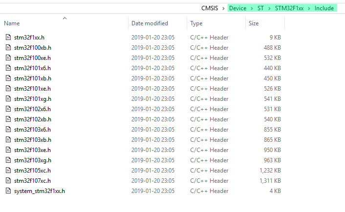
- For ST controllers, it is worth mentioning the header files, which ST themselves call the "CMSIS Device Peripheral Access Layer Header File". These are files for all ST controllers that contain all the necessary definitions (
#define), structures and constants, compatible with the CMSIS library. Technically, it’s enough to take the CMSIS files and a single ST header file with the peripherals description, and you can already write low-level code for the selected controller. To be honest, I've chosen this way for my first projects in order to learn the STM32 architecture better. Of course, such code isn't so portable compared to the code written with higher-level libraries (which, by the way, is debatable), but for a hobby it does not require perfect portability. Where do you get these header files? As you've probably already guessed, STM32CubeMX generates them for your project. Or you can use the same link to download the Cortex-M3 bundle from the ST website. They can also be downloaded from the unofficial GitHub projects like this one. These files should be placed in the CMSIS directory ("Devices" folder, designed exactly for such header files from controller manufacturers):
Well, let's keep our tradition and rewrite the same initialization code for the
F6pin again. We won't miss a single action from the originally generated code, but now use only the header file for the desired controller (for my debug board it's thestm32f1xx.hfile, which in turn includes thestm32f1xe.hfile) and CMSIS headers:1234567891011/* GPIO Ports Clock Enable */RCC->APB2ENR |= RCC_APB2ENR_IOPFEN;[[maybe_unused]] auto value = RCC->APB2ENR;/*Configure GPIO pin Output Level */GPIOF->BSRR = GPIO_BSRR_BR6;/*Configure GPIO pin : PF6 */GPIOF->CRL |= GPIO_CRL_MODE6_1 | GPIO_CRL_CNF6_0;GPIOF->BSRR = GPIO_BSRR_BS6;Only 5 lines of code and no function calls, but it's definitely more difficult to understand without the detailed comments. Here you can notice a strange line starting with [[maybe_unused]]. This is exactly one of the errata bugs of many STM32 controllers: when you turn on a peripheral (we enable the port
Fperiphreal clock), you need to read back the value of the peripheral configuration register (APB2ENRin our case). Otherwise, it is likely that the required clock will not be turned on during the execution of several following instructions. And we need this clock enabled instantly, because right after turning it on we start writing to the registers of theFport. If its clock is turned off, the values we write will not be stored in the registers, which are controlled by this clock. When using the HAL or LL libraries, this obscure code is hidden inside a macro or function that you call (__HAL_RCC_GPIOF_CLK_ENABLEorLL_APB2_GRP1_EnableClock, respectively), and you don’t need to do this yourself.The macros
GPIO_CRL_MODE6_1andGPIO_CRL_CNF6_0don't add any clarity to your code either. Without datasheet, you are unable to understand what is happening: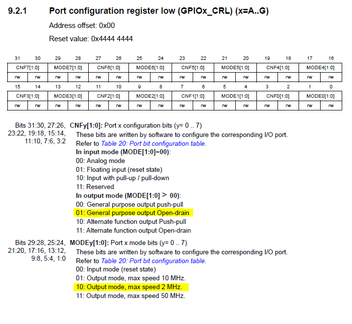
As you can see, writing something more or less complex in this manner will be unrealistic. You can try, but only if you do have a lot of free time. HAL and LL along with STM32 USB Device Library, although bulky, contain a lot of complex logic (e.g. USB HID protocol implementation or, say, code to run SPI with DMA). This logic has already been written and debugged for you, so that you can use it out of the box.
Experimenting with different options for writing code, I've even written my own small C++17 library, where all the same simple initialization code looks like this:
1234gpio::configure_gpio<gpio::set_output<gpio::gpiof<6>, gpio::out::open_drain,gpio::out::one, gpio::out::freq_2mhz>,gpio::enable_peripherals>();Here everything is clear, the code is checked during compilation and, in general, it's not tied to any particular controller or manufacturer at all. The main thing is that the controller has the
Fport with the pin #6. But I will not share this library yet, since it's too raw and hobby-level quality. - Third-party developers create custom libraries for Cortex-M3. One of the most well-known libraries is libopencm3. It has many high-level features, it is compatible with a large number of controllers with the Cortex-M3 core from different manufacturers, it is being actively developed, but it's still work-in-progress, which means that the interface of this library can change drastically. I haven't tried this library yet, but it seems a very good option. As a classic exercise, let’s write the same code to initialize the output of
F6:12345678rcc_periph_clock_enable(RCC_GPIOF);gpio_clear(GPIOF, GPIO6);gpio_set_mode(GPIOF, GPIO_MODE_OUTPUT_2_MHZ,GPIO_CNF_OUTPUT_OPENDRAIN, GPIO6);gpio_set(GPIOF, GPIO6);I guess, everything is simple and clear here, and comments are not needed!
- There's another USB library that I found: libusb_stm32. It's compatible with many ST controllers, it's compact enough and fast, and it's not an abandoned project. The code is decent and easy to read, you can use it to learn the tricks of working with ST controllers USB and USB OTG peripherals.
- There is a popular official operating system by ARM and controller manufactures, Mbed. It contains both the operating system code and the code to interact with peripherals of different controllers, as well as with various hardware devices (such as LCD displays and SD cards). It is free and is easily compiled for various debug boards with controllers based on Cortex-M cores.


Question 4. I've chosen the libraries, how do flash the controller?
Libraries are selected, now we can write code! We build it in the selected development environment. There should not be any difficulties with this, since the compilation process is simplified by development environments as much as possible. I will describe in more detail how to build a project using the Makefile only. If you generated a Makefile project using STM32CubeMX, then everything is simple: you can build your project using the make command. If you manually created a Makefile, or, for example, you want to rebuild the project for another controller, then you will need to find and replace the so-called linker script for the selected controller, as well as the file with the initialization code. Apparently, all development environments use such scripts when linking the project, but they find the right ones and configure them for you automatically.
Let's start with linker scripts. These files usually have the ld extension. For my debug board, this script is called STM32F103ZETx_FLASH.ld. You can take it from the project generated by STM32CubeMX for your controller, or find it in unofficial repositories on GitHub. You can also use the generator of these scripts from the libopencm3 library, or, as an option, write it yourself. Fortunately, there are enough manuals how to do this. So, what kind of scripts are these, and why aren't they required for AVR8? This is a set of instructions for the linker, which tells where each piece of data (RAM, stack, read-only memory) and code should be placed. Since the memory map is more complicated in Cortex-M3 than in 8-bit AVR, when flashing, you need to know where to put the interrupt vector table, the program data, the uninitialized data, etc. The linker script provides this information for the linker. You can write it yourself by examining the memory map for the Cortex-M3 core:

You'll also need to know memory area sizes for the particular controller you are using. Of course, it’s easier to find a ready-made linker script or generate it with some utility.
Now let's take a look at the initialization code. This is usually low-level code written in assembler that contains a table of interrupts and instructions which are executed after the controller was turned on or reset. Modern development environments generate it automatically for the desired controller, but in case you're curious (or in case you want to build a project using a Makefile from scratch) I will briefly discuss it. For my board, this code is contained in the startup_stm32f103xe.s file, and again I took it from the STM32CubeMX-generated project. The code contains the interrupt vector table for your controller (they are all different depending on which peripherals your controller has). In addition, there is the code for zeroing uninitialized data, the code that copies initialized data from program memory to the correct RAM addresses, and the code that executes the constructors and destructors of global C++ objects. Basically, there's everything necessary so that you could safely use the C and C++ language features and their standard libraries in your program. This initialization code will transfer execution to your program in the end.
I already described how to flash your controller. If you use a development environment, it can flash the chip for you. If you prefer Makefiles, then flash using STM32CubeProg or, as an option, using OpenOCD.
Question 5. The program is compiled and running. How do I debug it?
If you use a development environment, then, as you probably already know, it definitely supports debugging out of the box. You may need to tune it, but this should be done only once. For example, here's the debugging settings in VisualGDB (which can use OpenOCD as a backend):

As a general rule, all development environments support step-by-step debugging, breakpoints, tracking and changing memory contents, editing register and variable values. More or less everything that you can do when debugging a program for a desktop operating system.
If your project is Makefile-based, you can use the OpenOCD or gdb debuggers directly, which is usually less convenient.
No more questions!
So, this is probably everything you need to know to start coding for ARM controllers (and STMicroelectronics controllers with the Cortex-M3 core in particular, but not limited to!). I hope this information will be useful for people who were not familiar with these cores, and those willing to improve their skills and learn something new. I wish you happy coding and fewer bugs, and don't hesitate to ask your questions in the comments.